Key Concepts
A systematic approach to product development that ensures quality, efficiency, and innovation in engineering design processes.
Airfoil Design Methodology
This airfoil design methodology enables the consistent creation of high quality surfaces and easy modification through a robust and parametrised design.
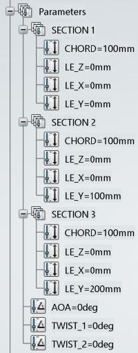
Airfoil Profile
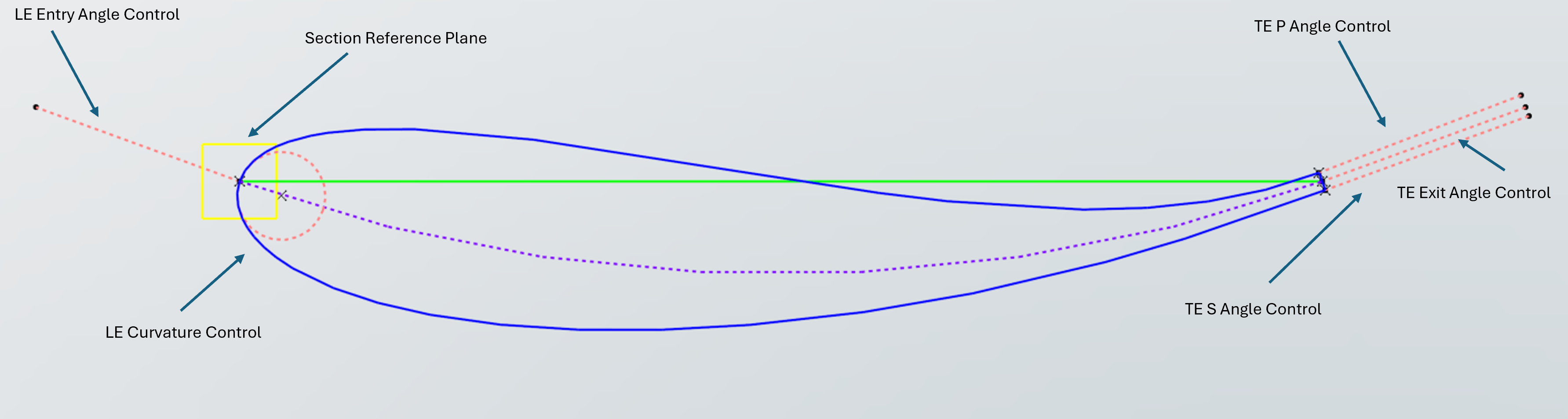
Primary airfoil section used as baseline for aerodynamic elements design.
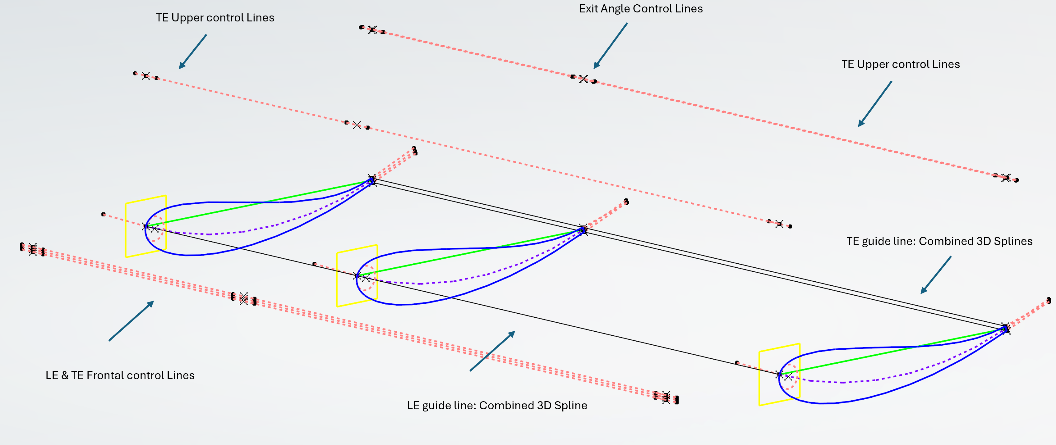
3D Wing Design
The methodology can be applied to high-quality complex surface design.
Wing Profile
Primary wing section used as baseline for 3D elements design.
Surface Detail
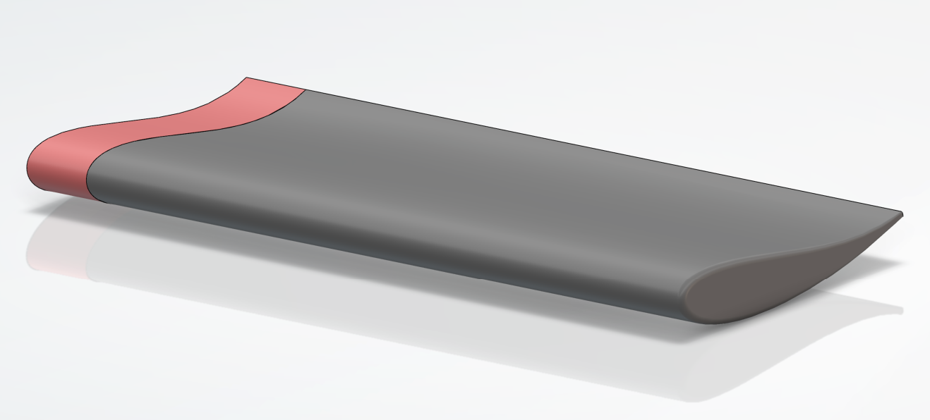
Detailed view of the wing surface and the tangent surface, used to maintain the high quality connectivity to the input structure and enable seamless symmetry creation.
CAD File Structure
A clear, consistent file and model structure reduces rework and speeds collaboration.
Project CAD Structure
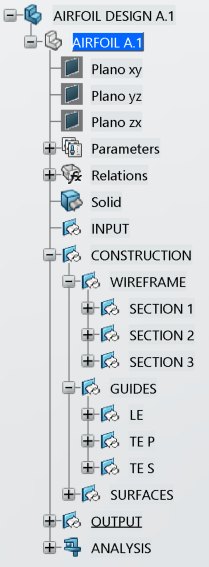
Main structure
The main structure is composed of three main folders that help organize the elements and enable fast knowledge transfer to other engineers of the team.
-
▶
Input
Input geometry is located in this folder to facilitate bounding boxes, tangencies and requirements of the new design. -
▶
Construction
Main folder where the designed elements are located. -
▶
Output
Final surfaces ready to be linked and assembled where needed.
Second Layer
Inside each main folder, the elements are divided to maintain a consistent structure and facilitate collaboration.
-
▶
Wireframe
Contains the reference geometry and the basic wireframe of the design. -
▶
Guides
Guide curves used to design complex surfaces. -
▶
Surfaces
Surfaces created from the wireframe and guides.
Color Code and Naming Conventions
Each type of element has a different color and style for rapid visual differentiation in the design and the navigation tree.
Parametrised Design
The most important characteristics of the design are parametrised and implemented through formulas to increase modification and iteration speed and robustness.
Legality and Quality Assurance
Ensuring designs meet regulatory requirements while maintaining the highest standards of surface quality through the Porcupine and connectivity analysis.
Regulatory Detail
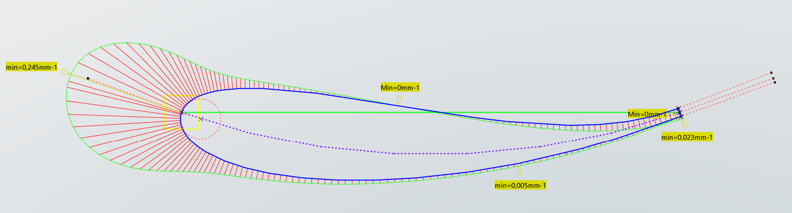
Procupine analysis used in the airfoil section to evaluate the quality of the section. The continuity showed by the tool ensures a high quality section with consistent curvature and tangencies.
Class-A surfacing
The design adheres to Class A surface standards ensuring a minimum of G2 continuity and G3 when needed.
- G0: Positional continuity, ensures there are no gaps between surfaces.
- G1: Tangent continuity, ensures surfaces are smoothly connected and share the same tangent angle at the connection point.
- G2: Curvature continuity, ensures the curvature of surfaces is continuous at the connection points.
- G3: Acceleration continuity, ensures the rate of change of curvature is the same at the connection points.
Porcupine Analysis
This tool is used to assess the quality of a surface through its sections. It provides insights into the continuity of the section.
Legality check
The Porcupine analysis can be used to control the minimum or maximum radius that is usually stated in the technical regulations. Advanced macros can be used to automatically check for regulatory compliance like the number of sections available in a plane or the containment inside boundary boxes.
Manufacturing standards
These quality checks can also be applied to the manufacturing process to ensure that the final product meets the desired specifications and quality levels as well as check for manufacturing limits like curvature radius or minimum surface width.