CAD Design Philosophy
A high-performance CAD methodology focused on delivering aerodynamically critical, regulation-compliant surfaces with maximum iteration speed.
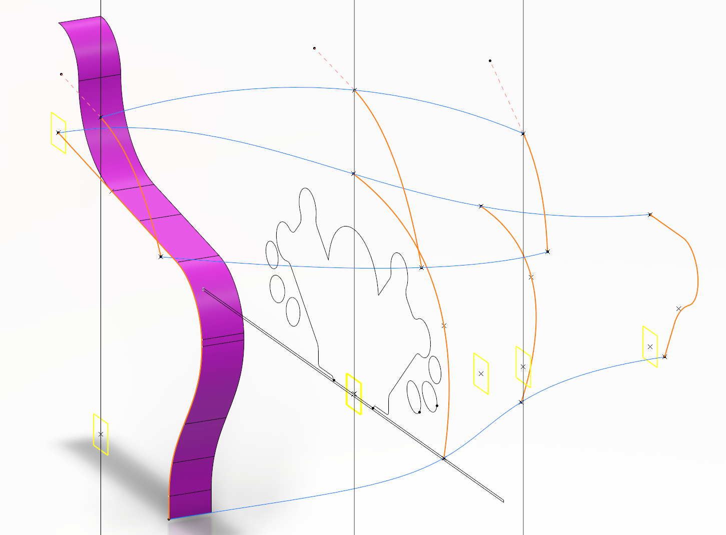
Skeleton-Driven Architecture
The bodywork's form is governed by a master skeleton of wireframe geometry. This approach ensures design intent is maintained and allows for rapid, predictable updates to surfaces when key parameters are modified.
The color-coded system defines the role of each element:
- ■ Pink: Primary tangent elements.
- ■ Orange: Cross-sectional profiles.
- ■ Blue: Guide curves for complex surfaces.
- ■ Yellow: Key reference planes.
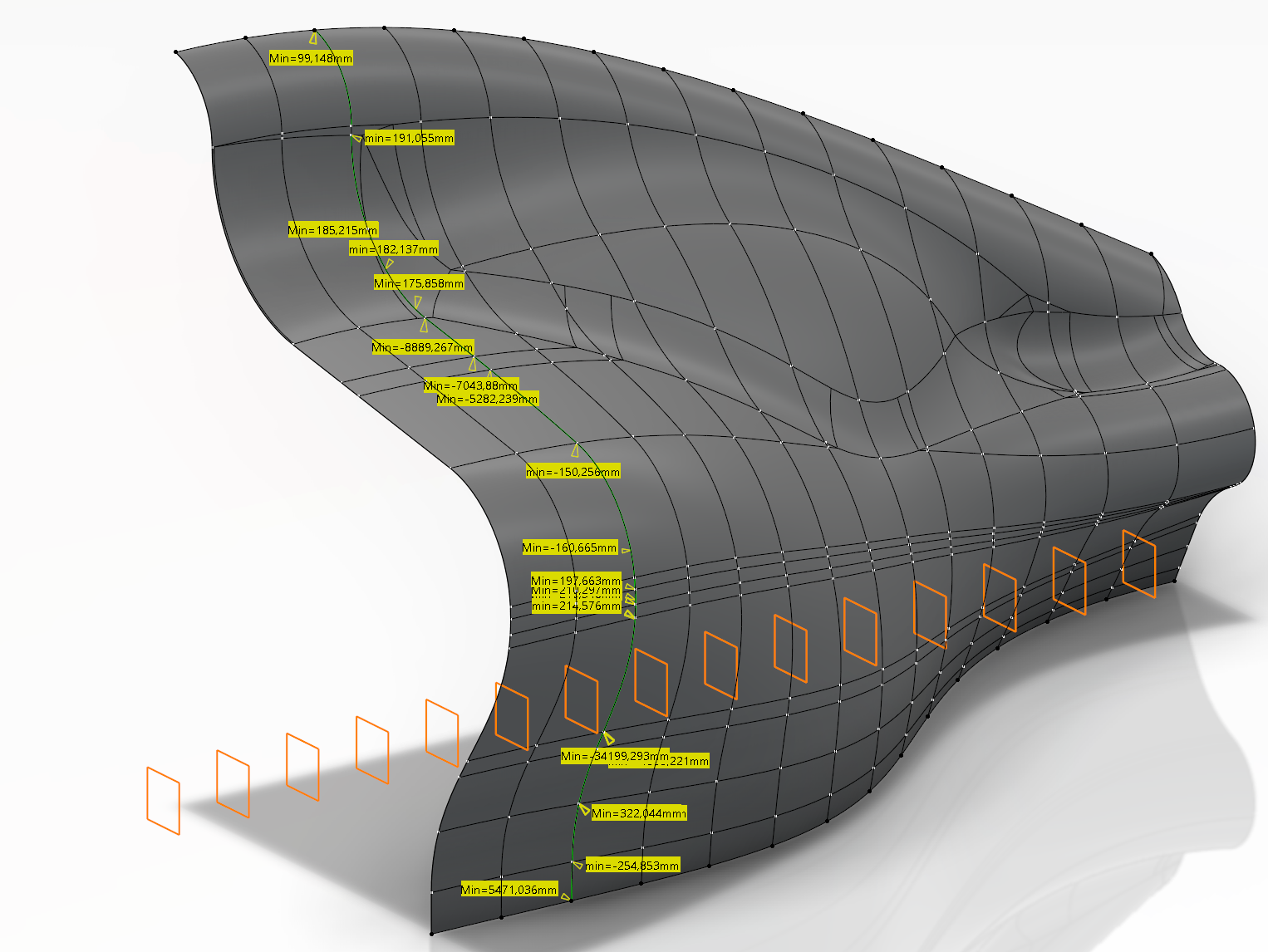
Curvature and regulation analysis
Used Porcupine Curvature analysis to validate surface quality and verify compliance with FIA regulations. In this case, various intersecting curves were created along the surface to check the radius of the sections at a 100 mm interval. The goal was to comply with the rule that states that the minimum radius of any cross-section of the bodywork is 75 mm.
Outcome: Guaranteed legal surfaces with high aerodynamic quality, ready for CFD with no rework.
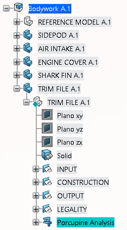
Structured for Collaboration
The model features a clean, logical tree structure (reference geometry, parts and trimmed output) with clear inner geometrical sets (Input, Construction, Output) and consistent naming conventions. This structure is critical for team integration, minimizing handover friction and accelerating the development loop.
Benefit: Reduced time for other engineers to understand, use, and build upon the design.
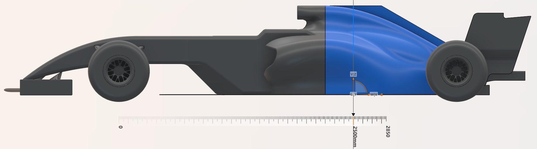
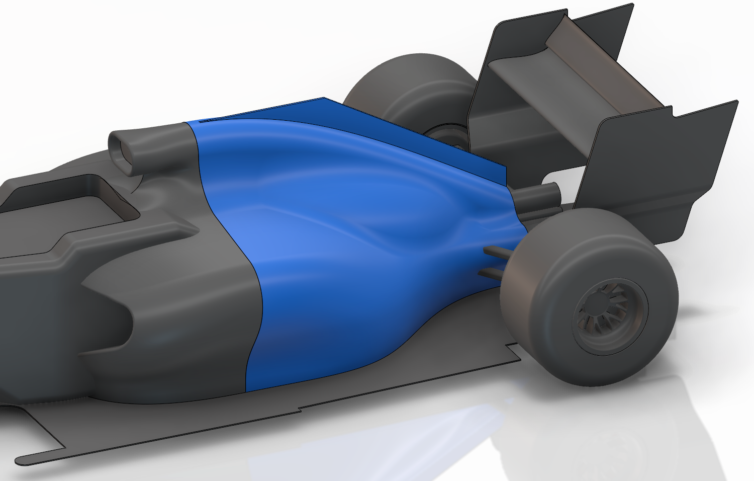
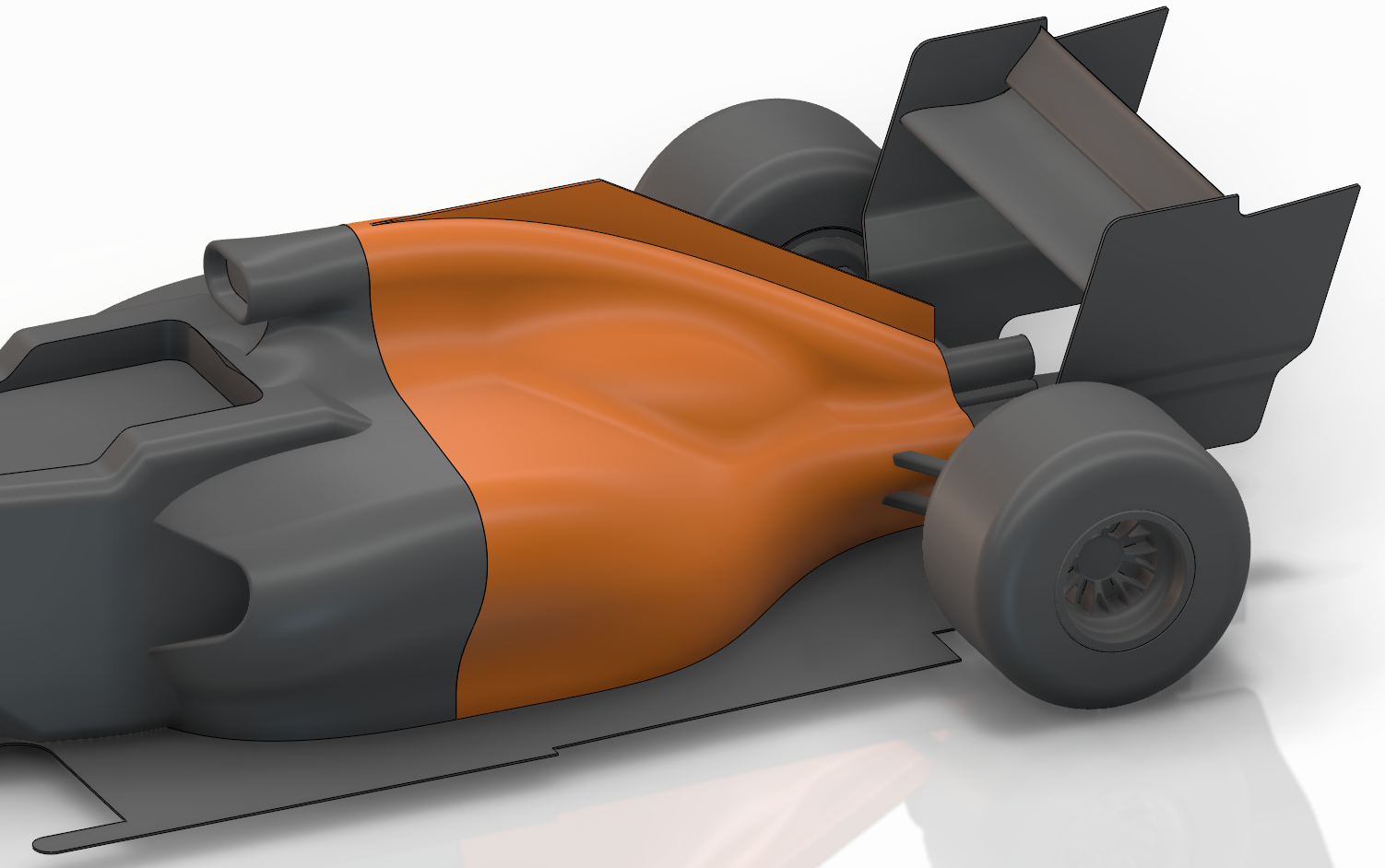
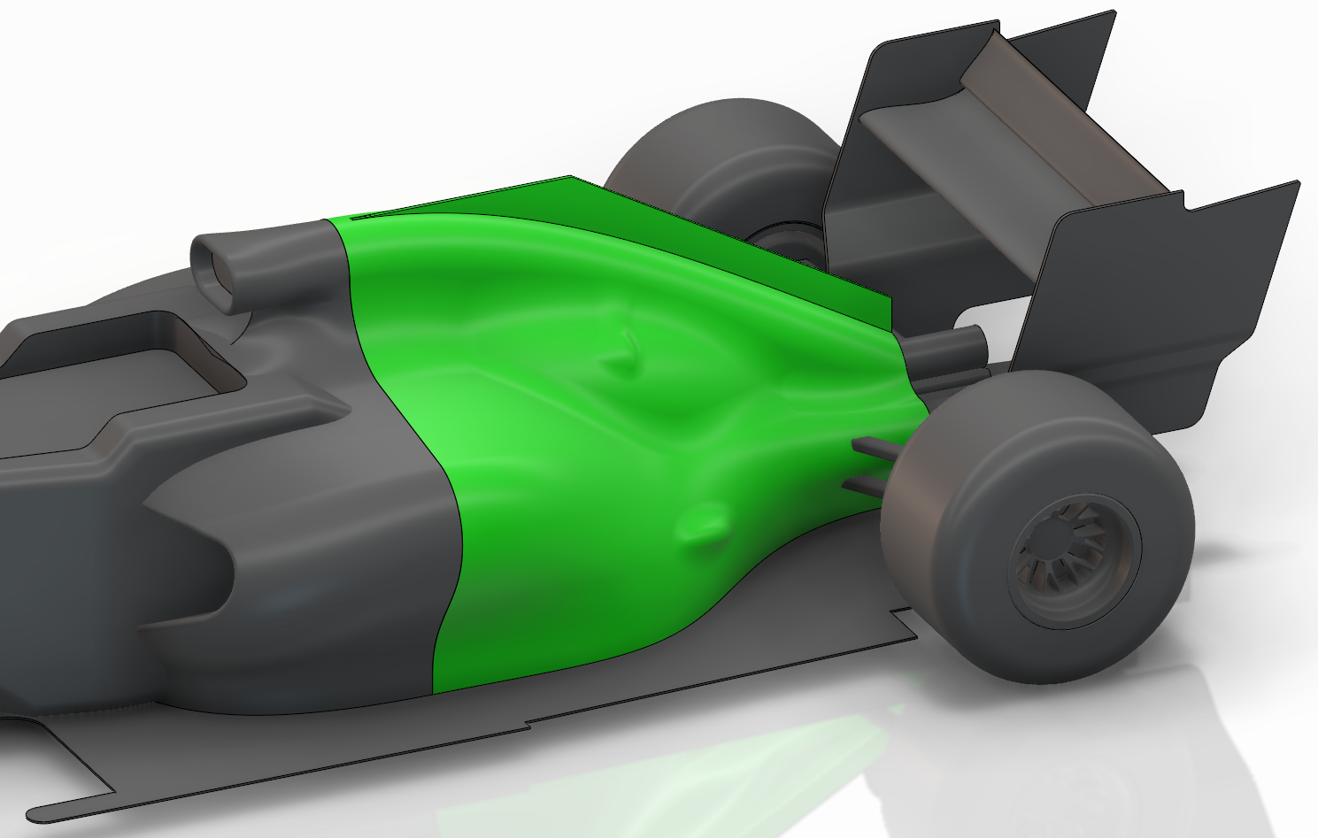
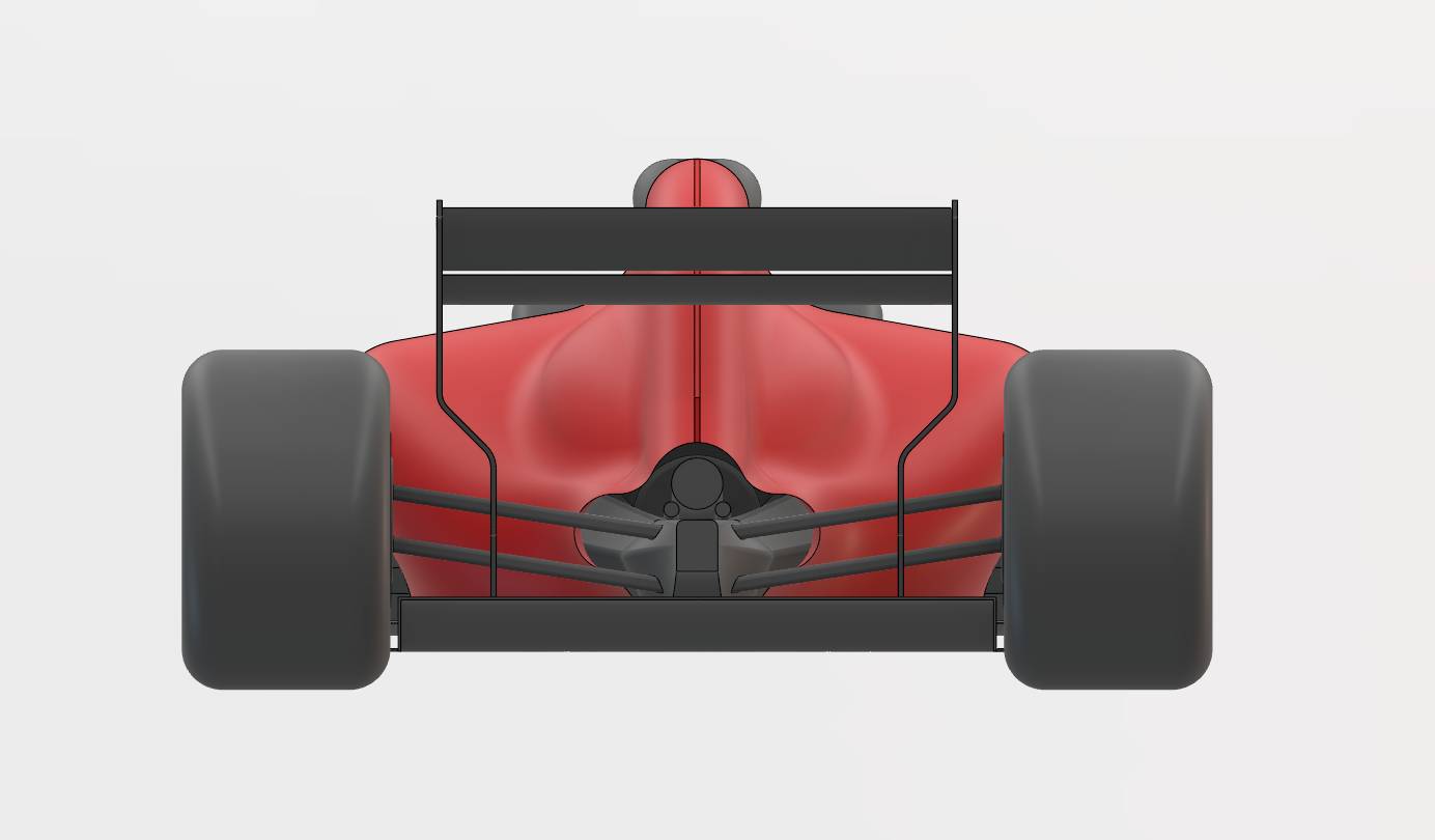
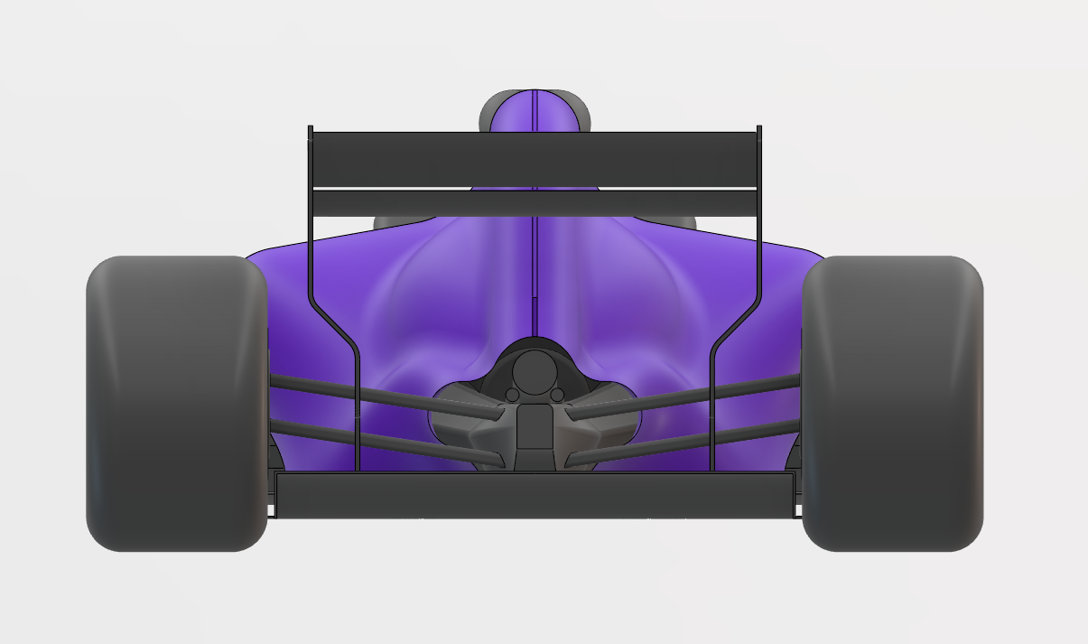
Aerodynamic Design Variants
Various aerodynamic packages were designed to explore different approaches to airflow management. These designs maintain the same side pod inlet while optimizing the bodywork for improved performance.
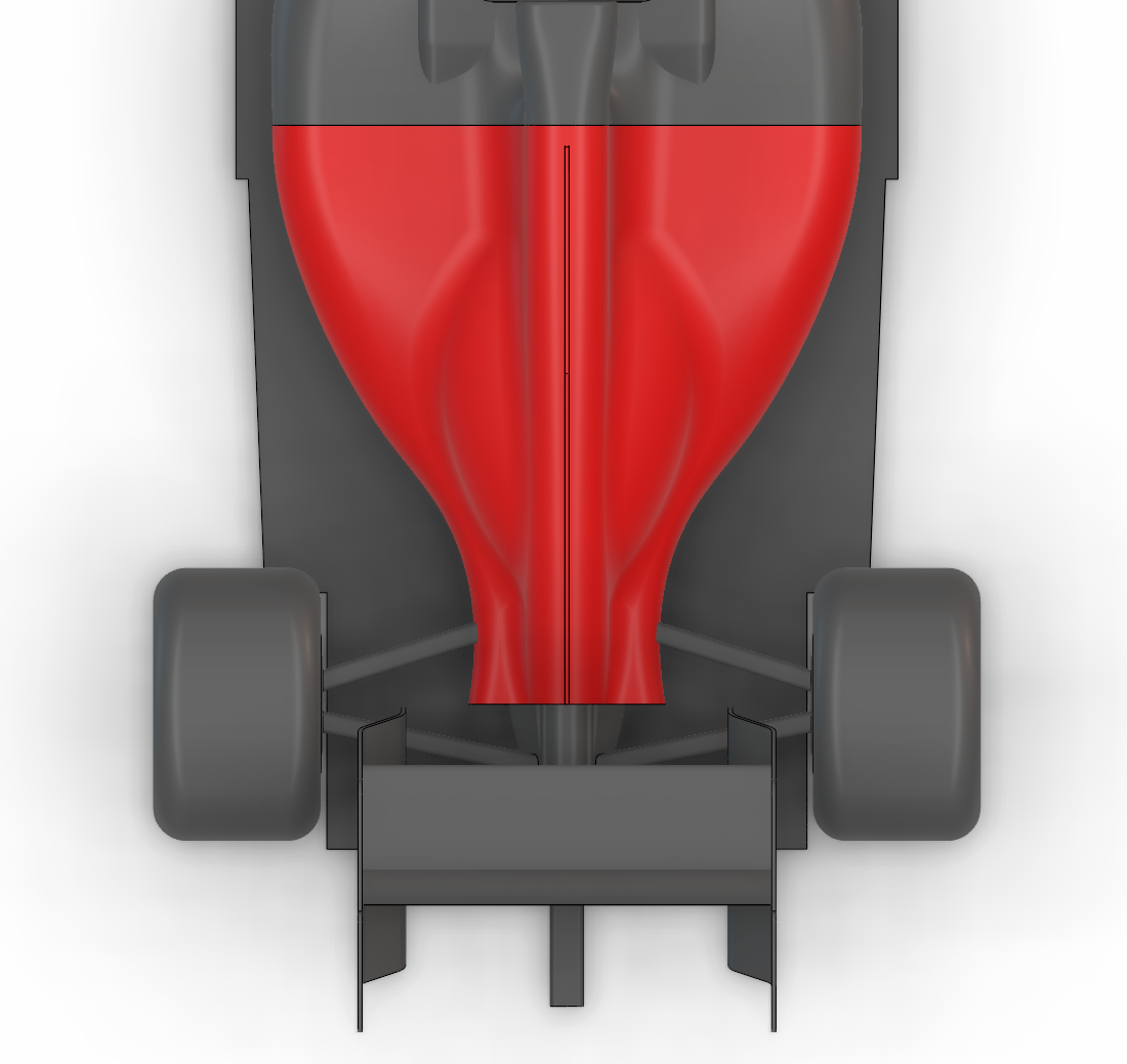
Baseline Design
A concept focused on smooth surfaces with minimal directional changes and disruptions to airflow. This design allows for a less complicated powertrain package.
- Simplified surfaces and airflow management
- Easier to comply with regulations
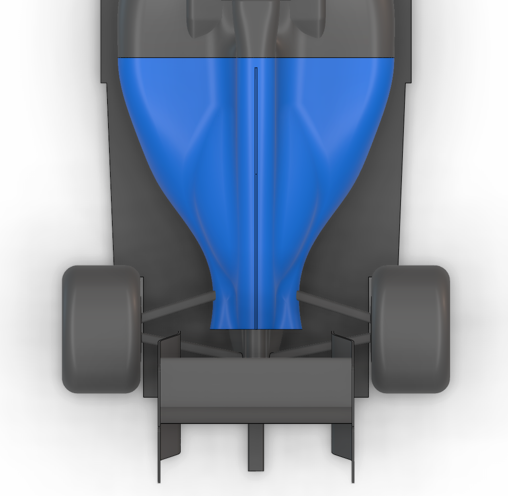
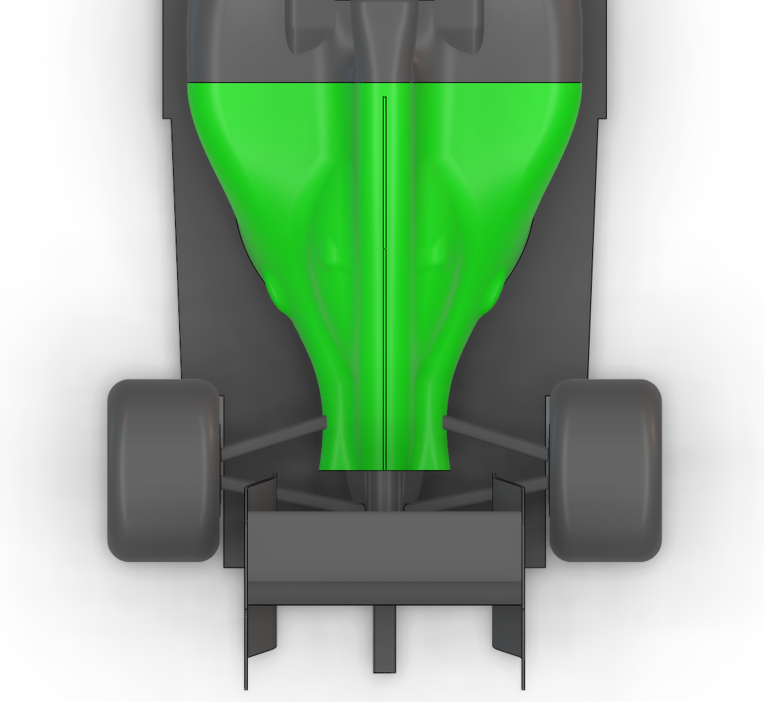
Size-Zero Design
This variant dramatically tapers the bodywork to minimize volume, aiming to improve airflow to the rear aerodynamic components.
- Reduced bodywork volume.
- Increased aerodynamic efficiency and improved airflow to rear-end
- Requires a highly compact powertrain package
- More difficult to manufacture
- Reduces cooling performance
Shrink-Wrap Design
A concept intentionally designed too tightly, covering protruding components with blisters, achieving an even bigger effect than the Size-Zero concept.
- The disruption of the flow caused by the blisters is minimal and worth the trade-offs.
- Volume reduced to the minimum
- Stricter manufacturing, cooling, and powertrain constraints than size-zero
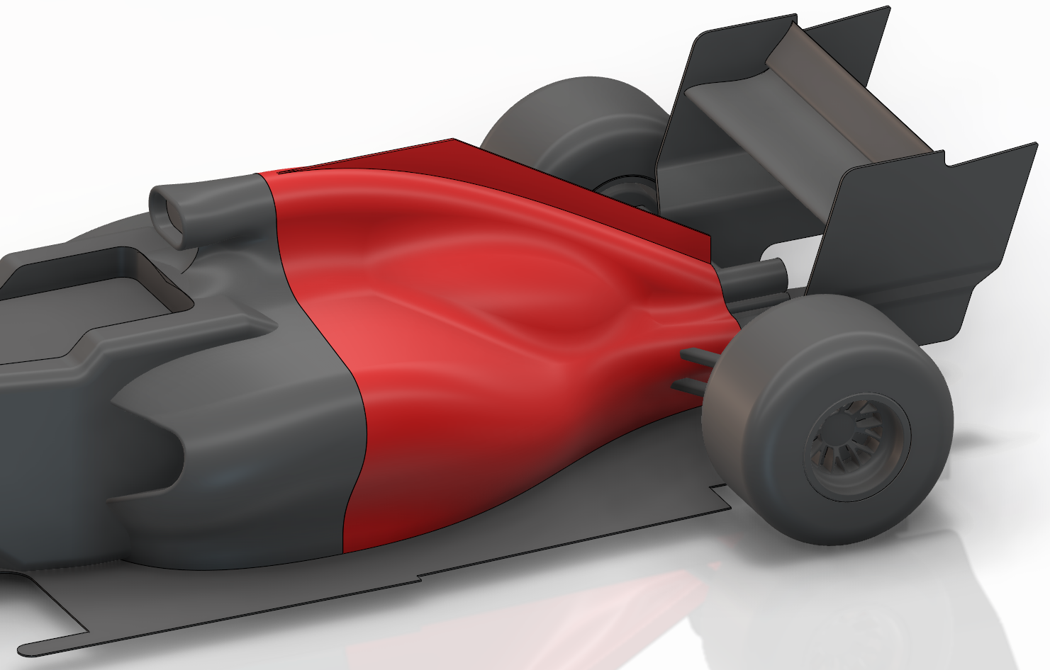
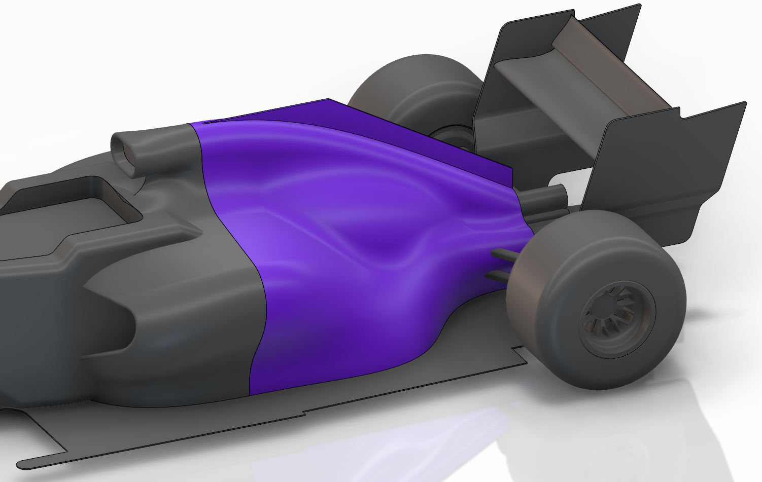
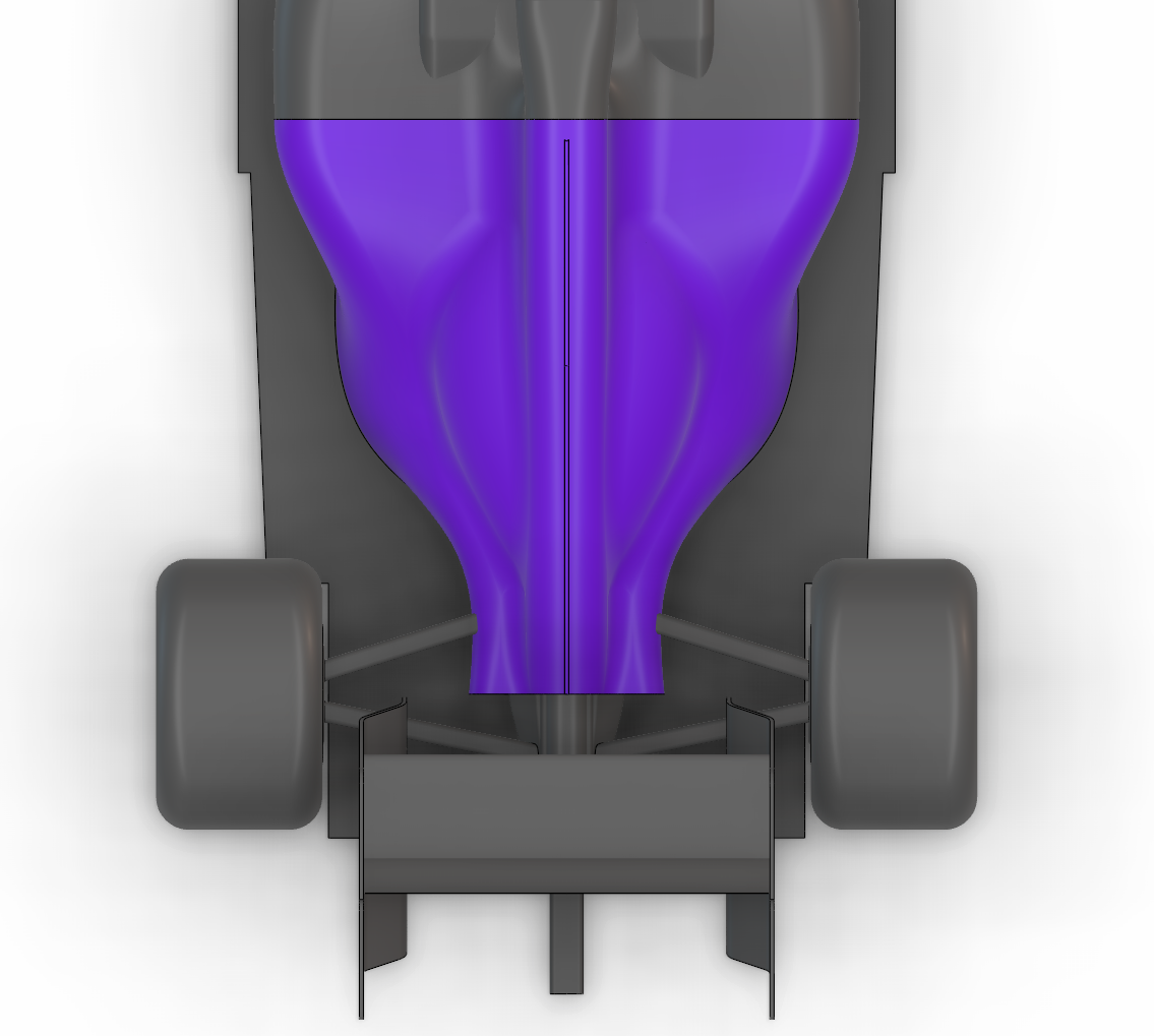
Undercut Design
This design features a deep undercut (coke-bottle with minimal curvature) to guide clean energetic air along the side of the bodywork with minimal directional changes, enhancing the performance of the rear aerodynamic components. This design tests the robustness of the wireframe and CAD design.
- Better airflow around the sides of the bodywork
- Center of gravity is higher due to component repositioning
High Downwash Design
This concept uses an extreme coke-bottle line to direct clean airflow downwards from the top of the car. It also allows for more components to be positioned in the side pods, reducing the height of the center of gravity.
- Pulls clean air from the top of the car to improve airflow to rear components
- Limited cooling performance due to restricted radiator exit
- Requires highly robust CAD due to the surface complexity
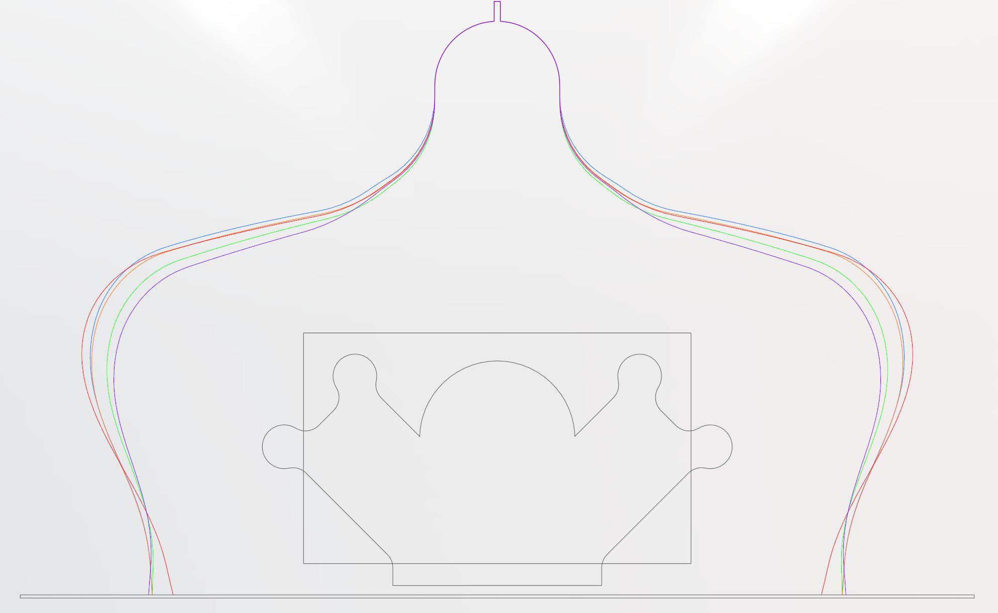
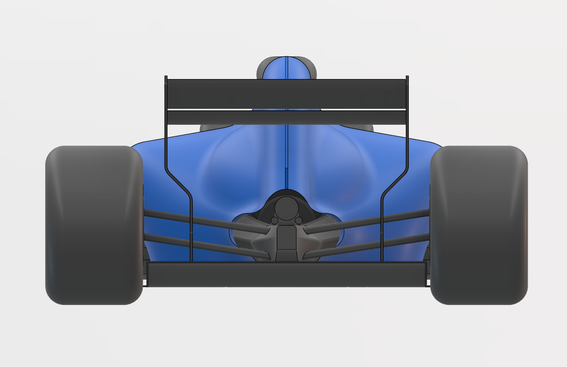
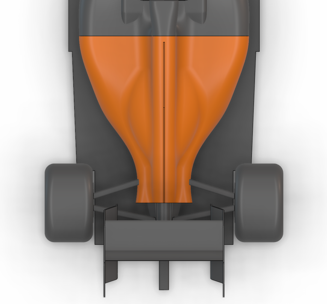
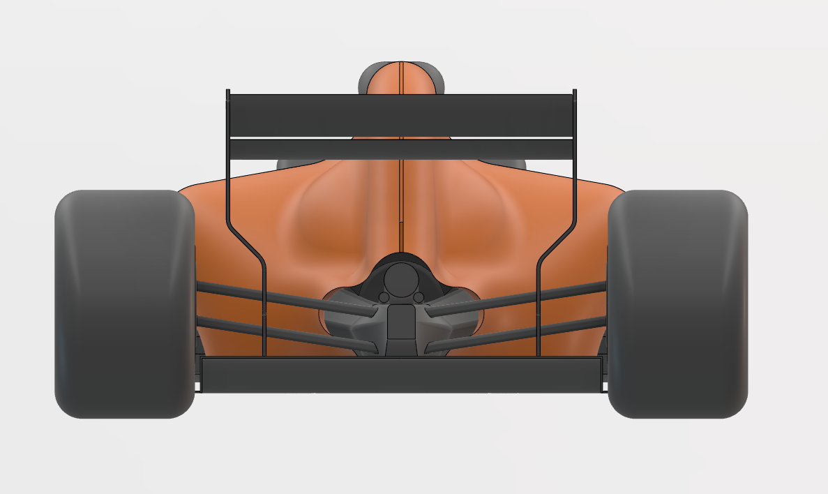
Cross-Section Comparison
Use the slider to move along the car's X-axis and compare the cross-sectional profiles of the five aerodynamic variants at that specific location.