Interactive Overview
Aerodynamic Package
Select any component node to explore the design in detail
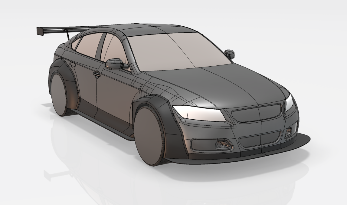
Aerodynamic Design
Comprehensive CFD study and aerodynamic package development for the Drivaer fastback model, optimising rear downforce, diffuser efficiency, and front balance using Star CCM+.
Interactive Overview
Select any component node to explore the design in detail
Component Detail
Project Objective
The aim was to perform a full aerodynamic study of the Drivaer fastback geometry and develop a high-performance aero package. Key components — rear wing, diffuser, and front splitter — were individually optimised to maximise downforce while minimising drag.
The project followed a systematic approach combining steady-state CFD simulations with parametric CAD iterations. Each component was characterised individually before integration into the complete vehicle package for final balance optimisation.
Simulation Software
Star CCM+
CAD Platform
3DEXPERIENCE / CATIA
CFD Method
Steady-State RANS
Validation
Mesh Independence Study
Components Analysed
3 Major Components
Key Technical Outcomes
CFD Validation
Mesh independence study confirming solution convergence and aerodynamic accuracy
Downforce Package
Integrated three-component aero package with improved front-to-rear balance
Parametric CAD
Fully parametric component designs enabling rapid geometry iteration and testing
Flow Analysis
Detailed flowfield visualisation identifying wake structures and pressure distributions