CAD Design Philosophy
This front wing design follows the workflow developed in the Design Methodology section using the Generative Shape Design toolbox in 3DExperience.
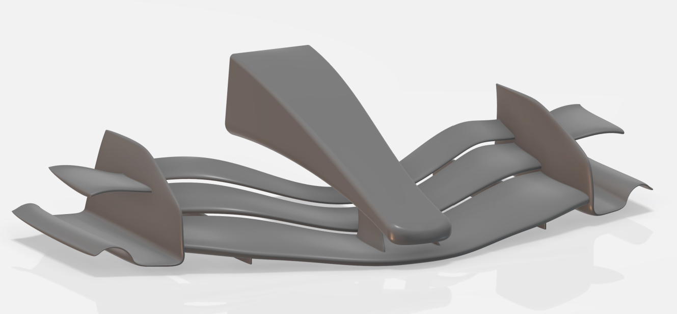
Front wing CAD design
The wing is built from a parametrised wireframe controlling all sections and guide lines for fast iteration maintaining high surface quality.
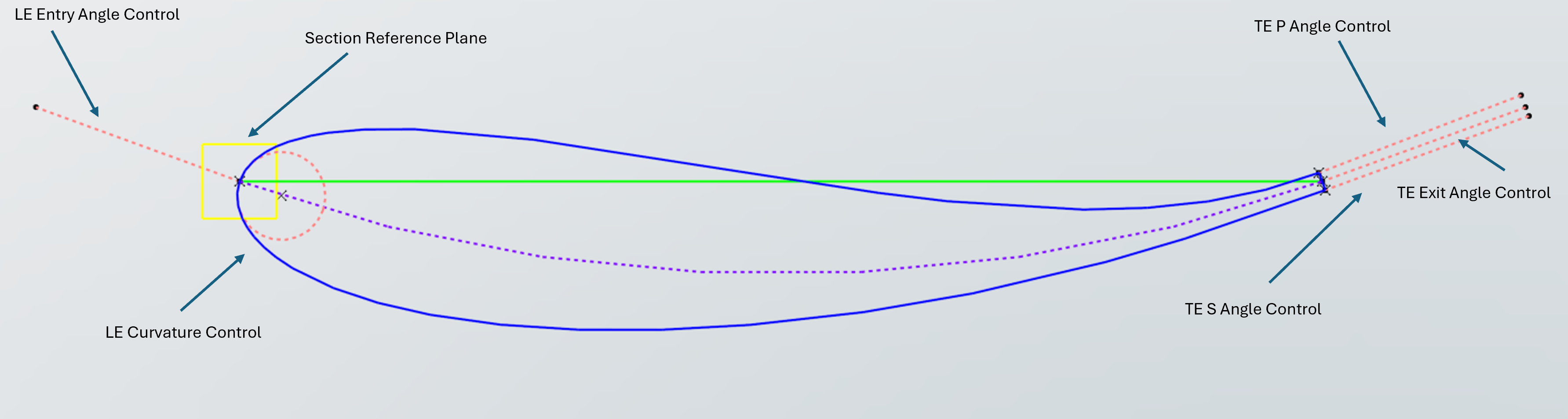
Airfoil Section Design
Customizable airfoil profile with precise control over camber and exit angles.
Nose design
The nose section was designed using various sections perpendicular to the X axis following a Methodology applicable to bodywork design.
Robust design
The design was carried out using intersections, projections and Extremums while applying trimming and rollover techniques for a robust, customizable design.
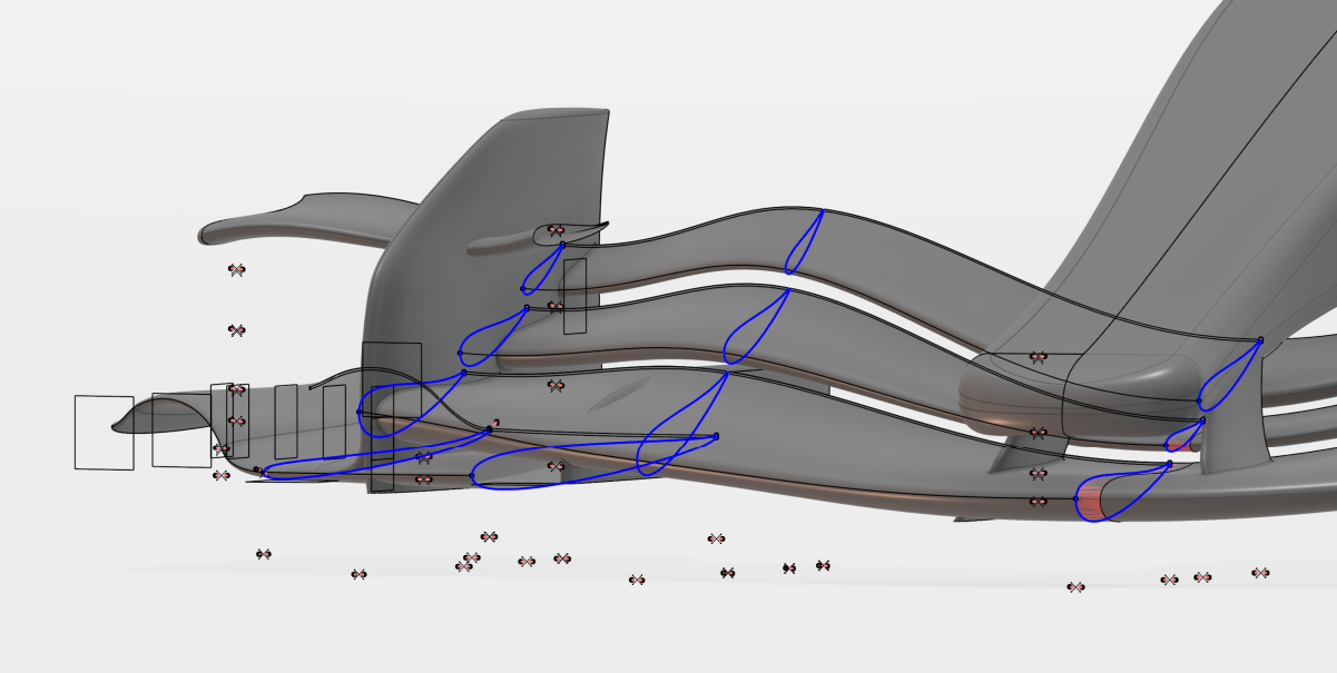
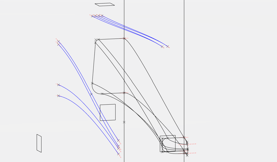
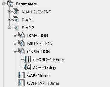
Surface guide lines
Surfaces are created using tangencies and 3D guidelines created by the combination of two splines using the tool combine. The Guidelines used in the flaps are linked to each other to maintain a uniform gap and overlap as defined in the parameters.
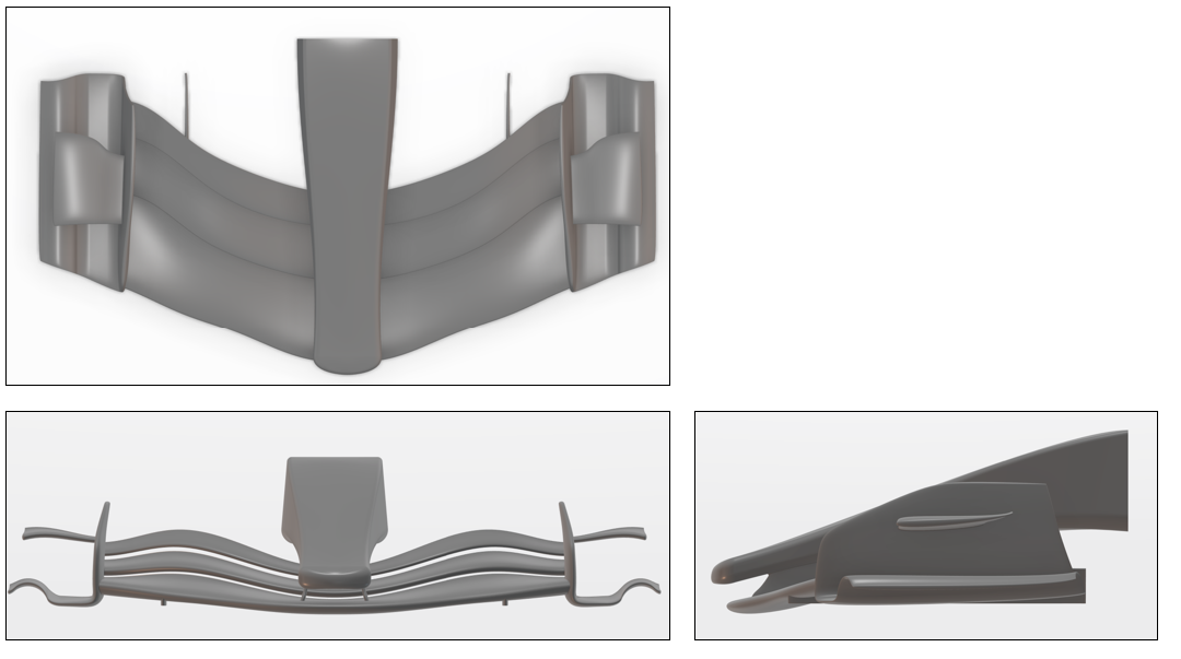
Aerodynamic analysis
Baseline design with an inwash Philosophy to make the most out of the new regulations.
Baseline Wing
A conservative flap setting with moderate camber for mid downforce scenarios.
Multi-element wing
Larger flap deflection and increased camber in flap 1 and 2 to take advantage of multi-element wing reenergization of the flow enabling higher AoA without separation of flow.
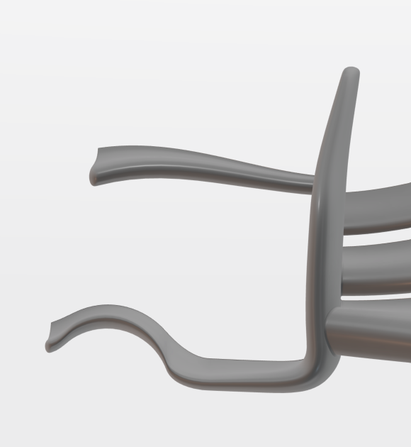
Inwash Endplate
The endplate and strake are designed not only to increase the efficiency of the wing reducing wingtip downwash, but also to seal the wheel turbulent structures from the downstream aerodynamic elements.
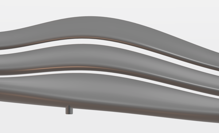
Surface Detail
High quality surface design with controlled curvature enabling optimal aerodynamic performance in future iterations after CFD analysis and wind tunnel testing.
Regulation Highlights
The analysis of the Formula One technical regulations (Issue 14) led to the creation of the reference volumes and surfaces used in the design process.
Reference volumes
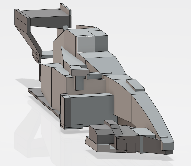
Illustration showing the Reference volumes designed using 3DExperience.
Dimensions & Placement
- Established the main dimensions and planes following the technical regulation.
- Height limits above the reference plane and forward/aft bounds for the front wing elements.
Elements & Radii Rules
- Leading/trailing edge definitions for manufacturing and wind tunnel model creation.
- Followed the Radii limitations on all elements with the use of the porcupine analysis tool.
Attachments & Assembly
- Endplate wings and attachments are assembled following the trimming rules.
- Fillets between each part are designed according to the regulations.